
2D CAD Design
Node Editing & Start Points
Reshape individual vertices, pull Bezier handles, bend straight spans into circular arcs, align multi-node subsets, and relocate green Start Points.
When a contour needs custom curvature, cleaner flow, or a specific entry corner for a profile toolpath, press N to enter Node Editing Mode.
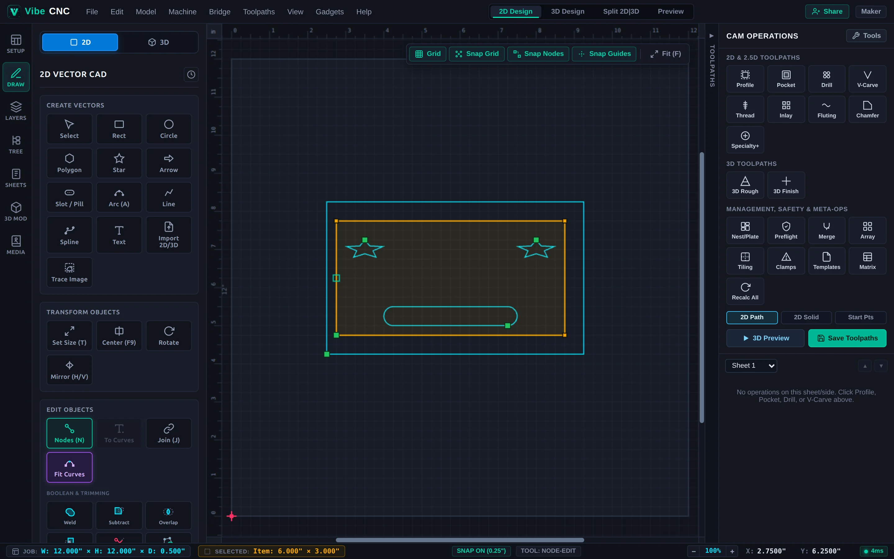
Node & Span Types
- Green Square (Start Point): Defines where a closed vector starts and ends, and where a Profile toolpath will plunge or ramp unless overridden by Keep Start Points / Optimize Start. Hover any vertex and press P to move the Start Point to an inconspicuous corner or waste edge.
- Black Square (Corner Node): Sharp direction change between adjacent spans.
- Blue Circle (Smooth Node): Tangent-continuous joint whose opposing Bezier handles stay collinear so curves never kink. Hover a node and press S to toggle Smooth vs Corner.
Bending Spans & Keyboard Actions
- Midpoint Arc Bending: Drag the midpoint marker on any straight line outward to bend it into a smooth circular arc with a live radius readout.
- Span Conversion: Hover over any span and press L (Line), A (Circular Arc), or B (Cubic Bezier).
- Insert / Delete / Cut: Hover a span and press I to insert a node; hover a node and press D to delete it; press C to cut a vector open at the hovered point.
Multi-Node Subset Manipulation
Drag a selection box in Node Edit mode (or Shift-click multiple vertices) to grab a subset of nodes. You can nudge, align horizontally/vertically, scale, or rotate just those nodes while leaving the rest of the part untouched. This is especially useful for lengthening a cabinet side panel without stretching the dado slots at either end.